I spent this week thinking more deeply and experimenting on designs for the earphone organiser.
Many designs came to my mind.
1. A design similar to the old manual measuring tape where you have to wind a rotor of sort to wind the tape back to into the spool.
2. Another design is similar to the copper braid container. A copper braid container has a flexible layer of plastic which allows the copper braid to be pulled from the spool with a slight tension, But it is one way. That means it is not meant to to be wound again(got to check this and make sure). What I am thinking is to make a spool on which the ear phone wire can be manually wound and taken out but a through a silicone opening covering winding slot of the spool. This is self closing and when required the wire can be extracted too.
I choose the winding mechanism similar to measuring tape to begin with. Since I like the idea and it is more mechanical in nature.
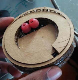
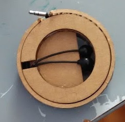
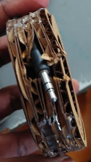
I worked a little more on the design I did last week and finally made some cuttings with the laser and made a cardboard working prototype. I was glad it was working as I imagined but it was a tedious to get corrugated carboard to slide over each other.
First protortype
 Files are at
https://www.dropbox.com/s/ixmxee9xb1gwgbb/all_f.svg?dl=0
You might have to use either glue gun of quick glue to assemble these. Part 1-5 are assembled in to one part which is the inner container and there are 5 of part 6 which is the sliding door. Right now we just slide the assembled pat1-5 and part 6 into each other. A little bit of dextirity is required here. I thick a little more clearence in the inner dia of part 6 will also do good.
I used glue gun due to non availability of the quick glue and it still worked. The sliding was a bit constricted because of friction of cardboard over cardboard.
To do
3D printed prototype
May be plastic molding and casting, for better sliding performance.
Improve the design to advanced level if possible(includes two different compartment, for wire from ear bud to the junction of the wire and another from the junction to plug)
Update
20/11/15
I finally made a 3d printer protype and it works perfectly.
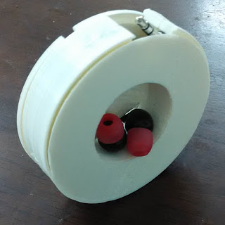

I split the sliding door into two because I want to get the details of the rails accurately. If I use support structures or try to print is with support structure too It wouldnt come properly.
Files at
https://www.dropbox.com/sh/7v718lwoarm4pmy/AACf-BgCQlmPBZ4A35MIxESka?dl=0
I split the sliding door into two because I want to get the details of the rails accurately. If I use support structures or try to print it without support structure, It wouldn't come properly. Later fevi quick or other such quick glue can be used to attach the two parts. I used the heat gun and few layer of pla from the support structure generate from printing the n1.stl to weld the both together. his doesnt seem to be a good idea the entire part stated warping and partially lost its form. This didn't create much difficulty but the it no more functioned perfectly. It still functioned to acceptable level. If you are trying to weld it with waste PLA then I suggest use of soldering gun and to keep soldering gun at 220 Celsius and try to weld them together.
Assembly
1. Print all the parts.
2. After printing the slide door top and bottom attach their flat side together.
3. Assemble the top and sliding dorr such that the top and the n1 part encase the sliding door. The top part has a grove on which the sliding door mates and the n1 has a ramp on which the ramp feature of the sliding door sits. Assemble them in proper orientation.
4. The top and n1 dont have holes so that screws can be used to assemble them. I used soldering gun again to weld them together when they are in proper orientation. The proper orientation is when the cavity of the top match the cavity on the n1. You can also try to drill holes and attach them.In next version I am going to provide the holes. A little adjustment of height is necessary. I used the support structure PLA in between n1 and top and welded them on to the n1. Later as I said before welded them all together with soldering gun when in proper orientation.
Many designs came to my mind.
1. A design similar to the old manual measuring tape where you have to wind a rotor of sort to wind the tape back to into the spool.
2. Another design is similar to the copper braid container. A copper braid container has a flexible layer of plastic which allows the copper braid to be pulled from the spool with a slight tension, But it is one way. That means it is not meant to to be wound again(got to check this and make sure). What I am thinking is to make a spool on which the ear phone wire can be manually wound and taken out but a through a silicone opening covering winding slot of the spool. This is self closing and when required the wire can be extracted too.
I choose the winding mechanism similar to measuring tape to begin with. Since I like the idea and it is more mechanical in nature.
I worked a little more on the design I did last week and finally made some cuttings with the laser and made a cardboard working prototype. I was glad it was working as I imagined but it was a tedious to get corrugated carboard to slide over each other.
First protortype
https://www.dropbox.com/s/ixmxee9xb1gwgbb/all_f.svg?dl=0
You might have to use either glue gun of quick glue to assemble these. Part 1-5 are assembled in to one part which is the inner container and there are 5 of part 6 which is the sliding door. Right now we just slide the assembled pat1-5 and part 6 into each other. A little bit of dextirity is required here. I thick a little more clearence in the inner dia of part 6 will also do good.
I used glue gun due to non availability of the quick glue and it still worked. The sliding was a bit constricted because of friction of cardboard over cardboard.
To do
3D printed prototype
May be plastic molding and casting, for better sliding performance.
Improve the design to advanced level if possible(includes two different compartment, for wire from ear bud to the junction of the wire and another from the junction to plug)
Update
20/11/15
I finally made a 3d printer protype and it works perfectly.
I split the sliding door into two because I want to get the details of the rails accurately. If I use support structures or try to print is with support structure too It wouldnt come properly.
Files at
https://www.dropbox.com/sh/7v718lwoarm4pmy/AACf-BgCQlmPBZ4A35MIxESka?dl=0
I split the sliding door into two because I want to get the details of the rails accurately. If I use support structures or try to print it without support structure, It wouldn't come properly. Later fevi quick or other such quick glue can be used to attach the two parts. I used the heat gun and few layer of pla from the support structure generate from printing the n1.stl to weld the both together. his doesnt seem to be a good idea the entire part stated warping and partially lost its form. This didn't create much difficulty but the it no more functioned perfectly. It still functioned to acceptable level. If you are trying to weld it with waste PLA then I suggest use of soldering gun and to keep soldering gun at 220 Celsius and try to weld them together.
Assembly
1. Print all the parts.
2. After printing the slide door top and bottom attach their flat side together.
3. Assemble the top and sliding dorr such that the top and the n1 part encase the sliding door. The top part has a grove on which the sliding door mates and the n1 has a ramp on which the ramp feature of the sliding door sits. Assemble them in proper orientation.
4. The top and n1 dont have holes so that screws can be used to assemble them. I used soldering gun again to weld them together when they are in proper orientation. The proper orientation is when the cavity of the top match the cavity on the n1. You can also try to drill holes and attach them.In next version I am going to provide the holes. A little adjustment of height is necessary. I used the support structure PLA in between n1 and top and welded them on to the n1. Later as I said before welded them all together with soldering gun when in proper orientation.