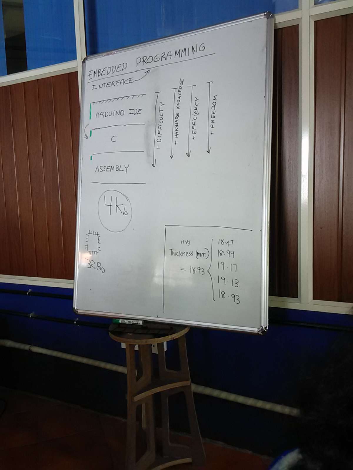
Consider the following methods of programing a microcontroller
Arduino ide- most user-friendly, many tools, quick, easy
C - intermediate difficult, need to have more hardware knowledge, more efficient in code handling and storing, more freedom to program.
Assembly lowest level of programing, need to have through understanding of the hardware also, more difficult, highly efficient in code handling and occupies least storage, and allows most freedom to program.
The setup program comes under
void setup(){
}
Every pin delivers- 5v max and 40ma current.
Programing
Blink
When you have a successful burn of bootloader you can start uploading the programs you wrote to the hello ftdi using the isp.
We used an example program, blink. It is located under examples->basics menu First we try to run the default program with only the pin numbers change to pin 8.
The following is the code.
void setup() {
// initialize digital pin 8 as an output. default will be 13 in the arduino example.
pinMode(8, OUTPUT);
}
// the loop function runs over and over again forever
void loop() {
digitalWrite(8,HIGH);
delay(1000);
digitalWrite(8,LOW)
delay(1000)
}
Now we try to switch on LED with the push button
Activate the internal pull up for stability using digitalWrite(); in the setup. If pull up is not activated then it will be susceptible to external noise. Essentially an open switch is connected to air and can be affected by electromagnetism of the air. If you have some potential and try to get your finger close to the circuit the switch condition will change. You might see it flickering or may be not, with conditions it changes. With internal pullup the pin get a high through internal circuit through internal resistor and only when the button is pressed will it be given a ground or 0 signal. In our case the push button is meant connected to gnd and so the logic should go like when the GND or LOW is detected in pin 7 the LED lights. And the normal state is the HIGH state.
Code:
void setup() {
// initialize digital pin 8 as an output.
pinMode(8, OUTPUT);
pinMode(7,INPUT);
digitalWrite(7,HIGH); // internal pullup
}
// the loop function runs over and over again forever
void loop() {
if (digitalRead(7)){
digitalWrite(8, LOW); // turn the LED on (HIGH is the voltage level)
}
else {
digitalWrite(8, HIGH); // turn the LED off by making the voltage LOW
}
}
Writing a program for communication
Make sure you select /dev/ttyUSB0 in tools->port. Normally it'll be unchecked.
Use USB to 6 pin ftdi cable to connect to the computer
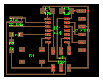
In the PCB component diagram we see that Tx and Rx are connected to pin0 and pin1 of the attiny. There is a confusion regarding the tx and rx sometimes the pin is are designated tx and rx implying that it goes to rx of the child device and sometimes it implies that tx is the transmitter and rx is the receiver of the parent device.
Initially we tried declaring rxpin as 1 and txpin as 0 as suggested by component diagram shown before, this didnt work for us. It worked on interchanging the rxpin and txpin declarations. This means that they point to the tx ad rx of the child device, we have to match the rx and tx. Here we consider the parent device as the hello ftdi and child device as computer. We will try to send things through this cable to the computer.
Here we programmed the hello fdti to send "print" word to the computer and light up the led when we send letter "c" to the hello fdti.
Code:
#include <SoftwareSerial.h>
const byte rxPin = 0;
const byte txPin= 1;
SoftwareSerial mySerial = SoftwareSerial(rxPin, txPin);
// the setup function runs once when you press reset or power the board
void setup() {
// initialize digital pin 13 as an output.
pinMode(8, OUTPUT);
pinMode(7,INPUT);
digitalWrite(7,HIGH);
// define pin modes for tx, rx:
pinMode(rxPin, INPUT);
pinMode(txPin, OUTPUT);
// set the data rate for the SoftwareSerial port
mySerial.begin(9600);
}
// the loop function runs over and over again forever
void loop() {
//listen to serial port
if (mySerial.read()=='c'){
digitalWrite(8,HIGH);
delay(1000);
//digitalWrite(8,LOW)
//delay(1000)
}
else{}
if (digitalRead(7)){
digitalWrite(8, LOW); // turn the LED on (HIGH is the voltage level)
}
else {
digitalWrite(8, HIGH); // turn the LED off by making the voltage LOW
mySerial.print("print");
}
}
Once you upload this code install gtkterm from ubuntu software center and configure its port to ttyUSB0.
When you press the button on the hello fdti it should print "print" on the gtk terminal.
Now to send from computer side : Open SerialMonitor from the arduino and send "c" to the ttyUSB0. The LED should blink.
update 19/11/2015
Making two board communicate with each other
I made a fabduino in week 4. and now going to try to make the fabduino(more info at http://puneethrj.github.io/w4d1.html and http://puneethrj.github.io/w4d2.html) and helloftdi wih led communicate with each other. As an indication I'm going to use the leds on the boards.
The code in hello ftdi remain the same as above. the following code needs to be uploaded to fabduino. The following code allows the fabduino to light up the led in the helloftdi in same frequency as the led in fabduino blink/ I have built upon the example code of blink from arduino ide for this.
To power the board and communicate I use the power from ftdi cable connected to the fabuino(to program it and after downloading keep it connected) and also the rx and tx from the same ftdi connection. You can either make a temporary solder for this or use jumper wires t o plug it into the holes behinf each terminal in ftdi connector towards the fabduino side.
Match the tx and rx of the helloftdi with fabduino, its not the opposite.
code:
#include <SoftwareSerial.h>
void setup() {
// initialize digital pin 13 as an output.
pinMode(13, OUTPUT);
Serial.begin(9600);
}
// the loop function runs over and over again forever
void loop() {
digitalWrite(13, HIGH); // turn the LED on (HIGH is the voltage level)
Serial.print("c");
delay(1000); // wait for a second
digitalWrite(13, LOW); // turn the LED off by making the voltage LOWSerial.print("d");
delay(1000); // wait for a second
}
This program worked and the led on helloftdi blinked in same frequency as the fabduino
Above we saw how fabduino can send signal to manipulate the helloftdi board.Arduino ide- most user-friendly, many tools, quick, easy
C - intermediate difficult, need to have more hardware knowledge, more efficient in code handling and storing, more freedom to program.
Assembly lowest level of programing, need to have through understanding of the hardware also, more difficult, highly efficient in code handling and occupies least storage, and allows most freedom to program.
Even though arduino is most popular prototyping tool, you are going to
hit a block with arduino as the problems you are trying to solve becomes
more complex. C and assembly level programming offer more freedom and
features to play around with at that level.
to put things in perspective,
Attiny has 4k bytes of memory to program, if programmed with arduino the
program will consume a lot storage, and clock cycles making it less
energy-efficient.
Some think that Atmel 328p- arduino chip which has more ram, storage is a solution. It costs more and has 120 pins and that means 120 things to debug if something goes wrong right away. It consumes more energy too.
In fabacademy - you have to fabricate your own arduino if you want to use an arduino.

Any microcontroller needs to be programmed for these
Interfaing
Embeded program
We set a fuse for microntroller, one time. A fuse is a setting you set for a microcontroller. Parameters of fuse:
fuse(clock(int,ext),speed,...)
Three kind of fuses- high, low and extended
extended has one setting- usually if you want to self program( a program that can reprogram)
Number of times you can program microcontroller - you can program a
microcontroller a limited number of times before is is not usable. It is
not infinite.
Programming on hello ftdi
You need to have a USB to mini USB cable with connector that is compatible with the connector on the ISP.
You need
Hello ftdi edited like showed in the earlier post.
Hello ftdi edited like showed in the earlier post.
6 pin Header cable.
FabISP
ftdi cable in the fablab.
Arduino IDE 1.6.5 or higher
Atttity addon
Connect the ISP to computer and connect the hello FTDI to the ISP using
the 6pin header cable(I also use ribbon cable to refer header cable).
Connecting header cable: When you consider the arrangement of the
ATtiny44 and 6pin ISP jumper arrangement you will see that they
are placed and oriented exactly alike in hellofdti and the FabISP board.
They remain the same in many of the circuits. You place the boards such
that the pair of atttiny and 6 pin jumper are oriented in same way side
by side, now the notch of the header connector should be in same
direction in both boards.
Arduino IDE settings
Program
In Tools go to and pick
Board-> ATTiny
Board-> ATTiny
Processor-> ATtiny 44
Programmer-> usbtinyisp
Clock -> 20Mhz External
Port-> ttyUSB0
Frank mentioned If you are not using external resonator and you tell
fuse that use external clock the you upload program- it cant be
programmed again until it is connected to external clock. I guess it
wont allow you to burn fuse again too with different settings.
Work around
Create pcb with resonator- to be plugged in and a optional circuit to which t an plugged in to .
A normal arduino board also can be used as an ISP. But it is not very
much entertained in fabacademy and you'd have to fabricate your own
arduino.
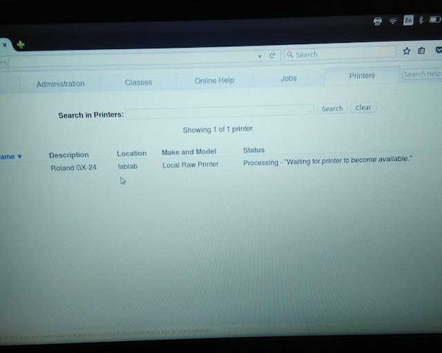
After settings you should burn the bootloader into the board.
use Tools->Burn bootloader
The burn succeeded.
Program
Program
Init and loop
Setup or init part of program- one time execution. It is used to setup input output pin or pwm.
Analog input- Use analog to digital converter to get meaningful data from an analog source.
Analog Output- PWM is used to output rather approximate analog output.
Analog Output- PWM is used to output rather approximate analog output.
The setup program comes under
void setup(){
}
Input- reads 0 or 5v,
Loop- is going to be executed in loop or a cycle.
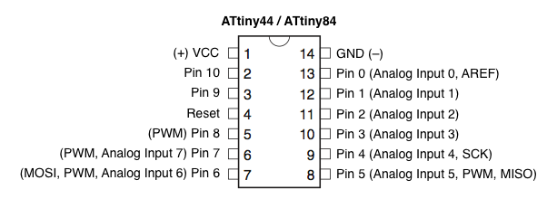
Pin number that arduno ide refers to is not same as atitiny pin
numbering so look at google for "arduino ide attiny pins". The following
is the image I found.
In our hello fdti we have connected led to pin 8 and button is connected to pin7.

We haven't used pull up resistor while dealing with the reset button. So
we activate it in arduino to use internal pullup with digitalWrite()
command, this should be in the void main or the setup segment.
Programing
Blink
When you have a successful burn of bootloader you can start uploading the programs you wrote to the hello ftdi using the isp.
We used an example program, blink. It is located under examples->basics menu First we try to run the default program with only the pin numbers change to pin 8.
The following is the code.
void setup() {
// initialize digital pin 8 as an output. default will be 13 in the arduino example.
pinMode(8, OUTPUT);
}
// the loop function runs over and over again forever
void loop() {
digitalWrite(8,HIGH);
delay(1000);
digitalWrite(8,LOW)
delay(1000)
}
Now we try to switch on LED with the push button
Activate the internal pull up for stability using digitalWrite(); in the setup. If pull up is not activated then it will be susceptible to external noise. Essentially an open switch is connected to air and can be affected by electromagnetism of the air. If you have some potential and try to get your finger close to the circuit the switch condition will change. You might see it flickering or may be not, with conditions it changes. With internal pullup the pin get a high through internal circuit through internal resistor and only when the button is pressed will it be given a ground or 0 signal. In our case the push button is meant connected to gnd and so the logic should go like when the GND or LOW is detected in pin 7 the LED lights. And the normal state is the HIGH state.
Code:
void setup() {
// initialize digital pin 8 as an output.
pinMode(8, OUTPUT);
pinMode(7,INPUT);
digitalWrite(7,HIGH); // internal pullup
}
// the loop function runs over and over again forever
void loop() {
if (digitalRead(7)){
digitalWrite(8, LOW); // turn the LED on (HIGH is the voltage level)
}
else {
digitalWrite(8, HIGH); // turn the LED off by making the voltage LOW
}
}
Writing a program for communication
We use SoftwareSerial headers for this purpose. We include SoftwareSerial
header file to create communication channels that enable us to communicate through bluetooth, serial, etc
Make sure you select /dev/ttyUSB0 in tools->port. Normally it'll be unchecked.
In the PCB component diagram we see that Tx and Rx are connected to pin0 and pin1 of the attiny. There is a confusion regarding the tx and rx sometimes the pin is are designated tx and rx implying that it goes to rx of the child device and sometimes it implies that tx is the transmitter and rx is the receiver of the parent device.
Initially we tried declaring rxpin as 1 and txpin as 0 as suggested by component diagram shown before, this didnt work for us. It worked on interchanging the rxpin and txpin declarations. This means that they point to the tx ad rx of the child device, we have to match the rx and tx. Here we consider the parent device as the hello ftdi and child device as computer. We will try to send things through this cable to the computer.
Here we programmed the hello fdti to send "print" word to the computer and light up the led when we send letter "c" to the hello fdti.
Code:
#include <SoftwareSerial.h>
const byte rxPin = 0;
const byte txPin= 1;
SoftwareSerial mySerial = SoftwareSerial(rxPin, txPin);
// the setup function runs once when you press reset or power the board
void setup() {
// initialize digital pin 13 as an output.
pinMode(8, OUTPUT);
pinMode(7,INPUT);
digitalWrite(7,HIGH);
// define pin modes for tx, rx:
pinMode(rxPin, INPUT);
pinMode(txPin, OUTPUT);
// set the data rate for the SoftwareSerial port
mySerial.begin(9600);
}
// the loop function runs over and over again forever
void loop() {
//listen to serial port
if (mySerial.read()=='c'){
digitalWrite(8,HIGH);
delay(1000);
//digitalWrite(8,LOW)
//delay(1000)
}
else{}
if (digitalRead(7)){
digitalWrite(8, LOW); // turn the LED on (HIGH is the voltage level)
}
else {
digitalWrite(8, HIGH); // turn the LED off by making the voltage LOW
mySerial.print("print");
}
}
Once you upload this code install gtkterm from ubuntu software center and configure its port to ttyUSB0.
When you press the button on the hello fdti it should print "print" on the gtk terminal.
Now to send from computer side : Open SerialMonitor from the arduino and send "c" to the ttyUSB0. The LED should blink.
update 19/11/2015
Making two board communicate with each other
I made a fabduino in week 4. and now going to try to make the fabduino(more info at http://puneethrj.github.io/w4d1.html and http://puneethrj.github.io/w4d2.html) and helloftdi wih led communicate with each other. As an indication I'm going to use the leds on the boards.
The code in hello ftdi remain the same as above. the following code needs to be uploaded to fabduino. The following code allows the fabduino to light up the led in the helloftdi in same frequency as the led in fabduino blink/ I have built upon the example code of blink from arduino ide for this.
To power the board and communicate I use the power from ftdi cable connected to the fabuino(to program it and after downloading keep it connected) and also the rx and tx from the same ftdi connection. You can either make a temporary solder for this or use jumper wires t o plug it into the holes behinf each terminal in ftdi connector towards the fabduino side.
Match the tx and rx of the helloftdi with fabduino, its not the opposite.
code:
#include <SoftwareSerial.h>
void setup() {
// initialize digital pin 13 as an output.
pinMode(13, OUTPUT);
Serial.begin(9600);
}
// the loop function runs over and over again forever
void loop() {
digitalWrite(13, HIGH); // turn the LED on (HIGH is the voltage level)
Serial.print("c");
delay(1000); // wait for a second
digitalWrite(13, LOW); // turn the LED off by making the voltage LOWSerial.print("d");
delay(1000); // wait for a second
}
This program worked and the led on helloftdi blinked in same frequency as the fabduino
Now we try to send a signal to fabduino from helloftdi and try to make the led in fabduino blink on click of the push button on helloftdi.
Again the code in helloftdi remains the same but we change the code in fabduino. Make sure you unplug jumper cabbles coming from helloftdi board from the ftdi terminals on fabduino before you upload code to fabduino by computer.
code:
#include <SoftwareSerial.h>
void setup() {
// initialize digital pin 13 as an output.
pinMode(13, OUTPUT);
Serial.begin(9600);
}
// the loop function runs over and over again forever
void loop() {
if (Serial.read()=='print'){
digitalWrite(13,HIGH);
}
else{
digitalWrite(13,LOW);}
}
I couldnt verify if this worked due to lack of time.